Skip to content
02

CompleteJanuary 2026 – June 2026

Stryker logo

Test fixtures for a camera head, coupler and camera control unit: laser intensity, interface reliability, focus ring torque, and front cover vibration testing.

Role
R&D Mechanical Engineering Co-op
Organization
Stryker Endoscopy
Timeline
January 2026 – June 2026
Tools
SOLIDWORKS, Creo, MJF + MJP printing, Instron, Torsional Instron, Vibration table, Manual mill + lathe
Project type
R&D Engineering · Design for Test · Mechanical Reliability · Verification + Validation · Medical Devices
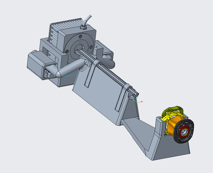
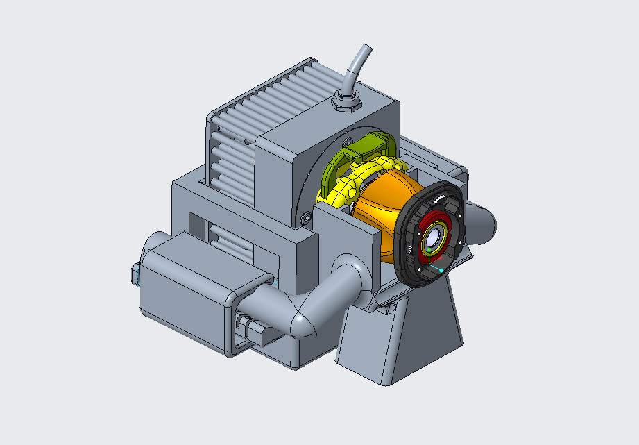
CAD assembly of the laser intensity fixture in its full configuration, with the source, a scope body and the sensor in line along a rail.
02.0 — LASER INTENSITY FIXTUREThe laser intensity fixture as built, after five revisions.

Specifications

Print processes
MJF, MJP for alignment-critical features
Test types
Optical, torque, vibration, lifecycle
Subsystems
Camera head, coupler, camera control unit
  • R&D Testing
  • Experimental Design
  • Medical / Human-Centered Design
01

Laser intensity fixture

A laser intensity testing setup, with and without a scope in the path, at variable distance.

  • Rev 1 — basic centering, discrete distance markings.
  • Rev 2 — changed clearances, stronger base.
  • Rev 3 — added insert system and y-axis lock.
  • Rev 4 — switched critical alignment features to MJP.
  • Final — complete locking system, constrained through the coupler instead of the scope, coupler-only version added.
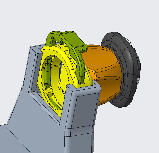
CAD view of a test fixture with a clamped bore, locking screws and a sliding carriage.
02.1 — FINAL REVISIONFinal revision: complete locking system, constrained through the coupler.
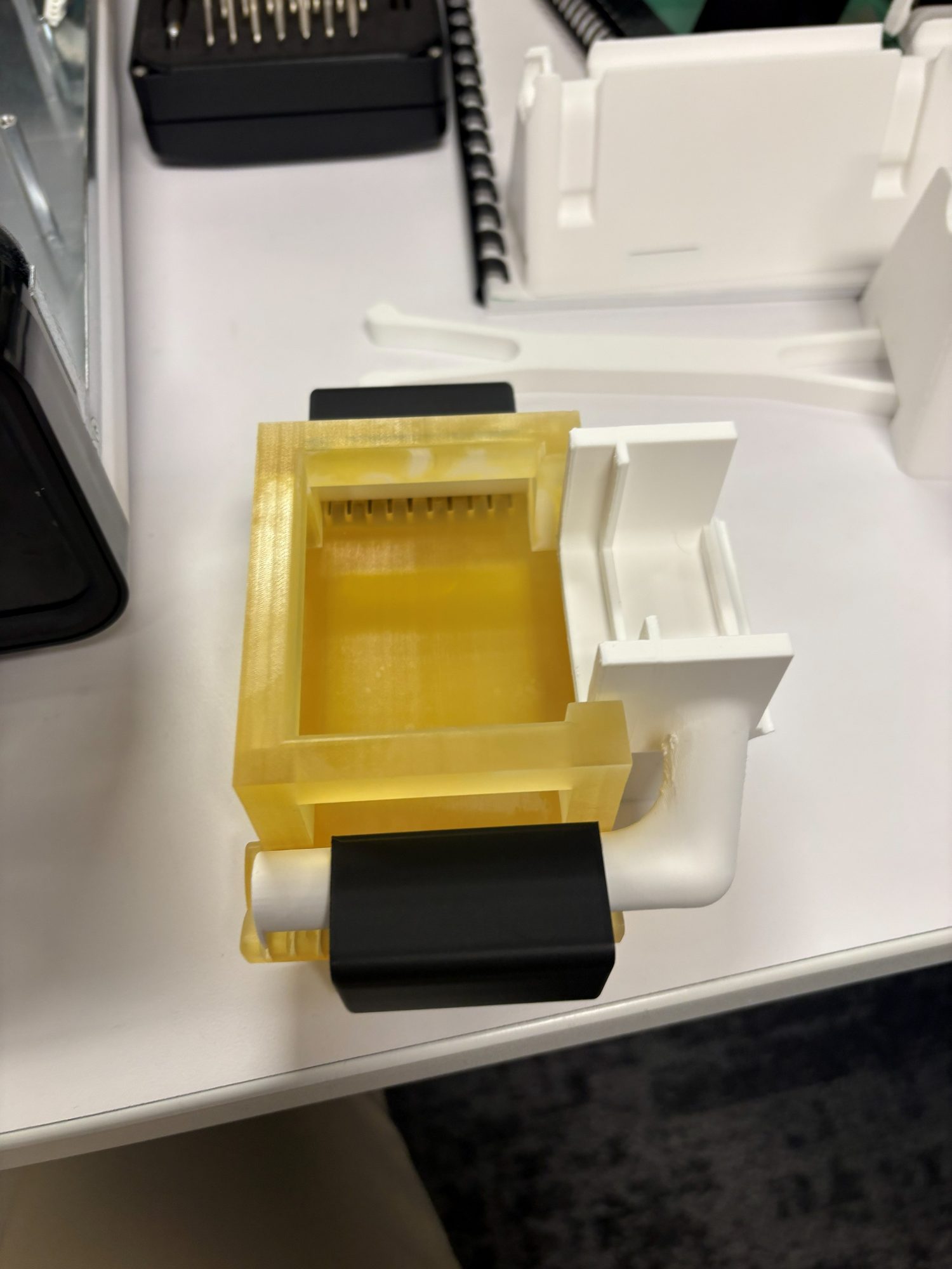
A printed and machined fixture clamped on a bench rail holding an optical component.
02.2 — AS BUILTThe fixture in use, with printed inserts seated.
CAD assembly of a test fixture with a sensor head mounted in line with a clamped optical component.
02.13 — LASER FIXTURE ASSEMBLYLaser intensity fixture with the sensor mounted.
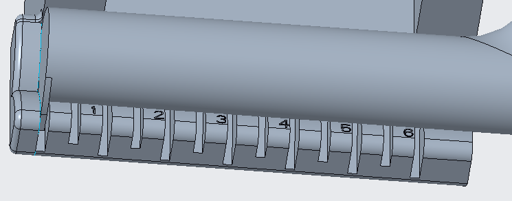
CAD detail of a cylindrical rail with numbered graduation marks along its length.
02.14 — DISTANCE MARKINGSDiscrete distance markings along the rail.
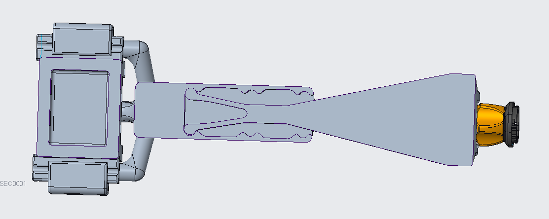
CAD side view of a long test fixture with a tapered scope body between the source and the sensor.
02.19 — FULL VERSIONThe full version, with a scope in the optical path.
CAD detail of a clamped interface between a fixture body and a scope.
02.20 — FULL VERSION DETAILScope interface on the full version.
02

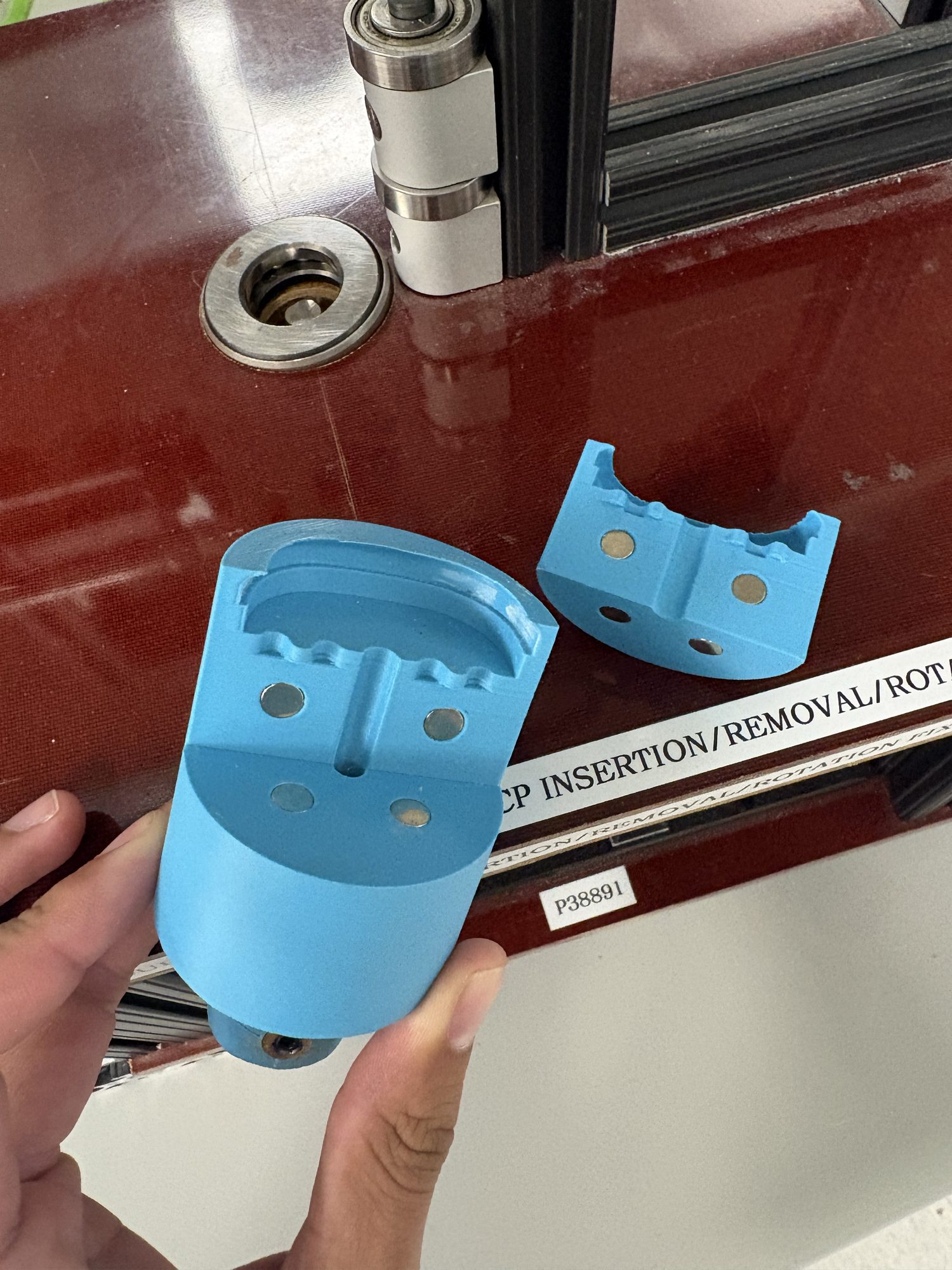
Focus ring fixture

A focus ring geometry change meant actuation torque had to be tested across the lifecycle, across different fin styles.

I used this fixture to perform torsional Instron testing and torque gauge testing.
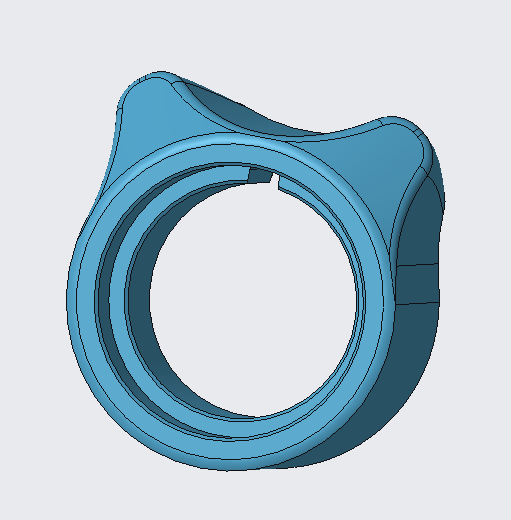
CAD view of a circular fixture with a toothed insert for gripping a focus ring.
02.5 — FIN VARIANTSInterchangeable inserts let one setup cover every fin style.
A fixture mounted in a torsional test frame gripping a ring-shaped component.
02.6 — TORSIONAL TESTMounted for torque measurement across lifecycle.
CAD view of a fixture wrapped around a cylindrical camera head body, gripping the focus ring collar.
02.10 — PENDULUM FOCUS RING FIXTUREThe pendulum focus ring fixture.
CAD view of a ring collar with raised fins on its outer face.
02.11 — FIN GEOMETRYOne of the fin styles the torque test had to cover.
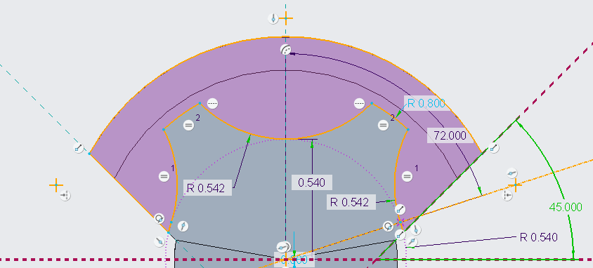
A dimensioned CAD sketch of a curved fin profile with radii and angles called out.
02.12 — FIN SKETCHFin profile, dimensioned.
03

Interface mechanical reliability

Simulates scope use with a coupler, and fully constrains the next-generation coupler to the test fixture.
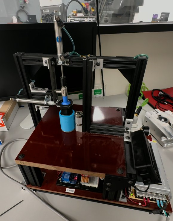
A test rig built from extrusion, with a coupler clamped upright beneath a linear actuator on a bench.
02.3 — RETENTION FIXTURERetention fixture — the coupler is fully constrained to the test rig.
A test fixture mounted in a load frame with a coupler clamped in position.
02.4 — ON TESTSet up for a mechanical reliability run.
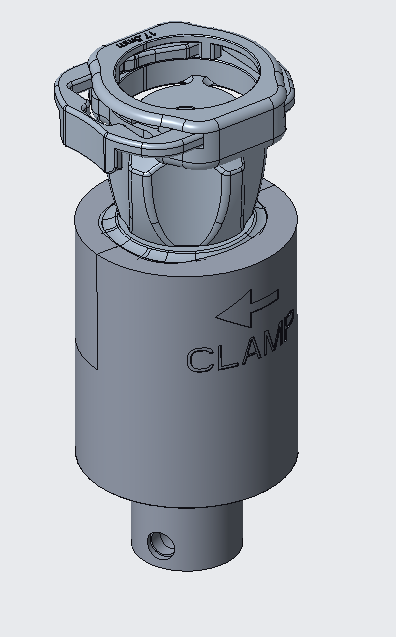
CAD view of a cylindrical clamp body with a tapered collar and a cross-drilled base.
02.15 — CLAMP BODYThe clamp body, labelled for orientation.
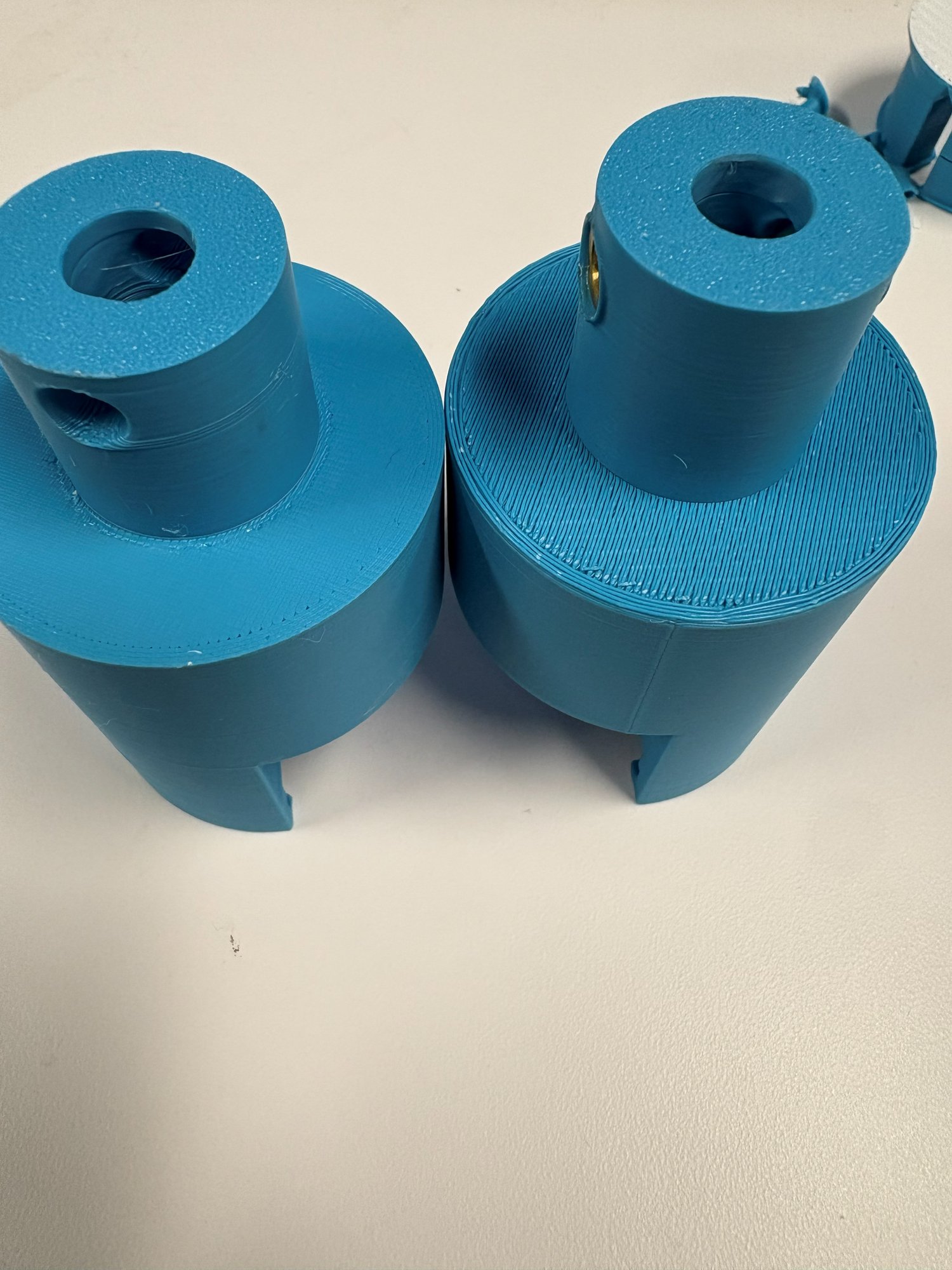
Two teal 3D-printed conical fixture bodies on a bench before assembly.
02.16 — PRINTED PARTSPrinted clamp components, as they came off the machine.
04

Camera control unit — front cover and vibration

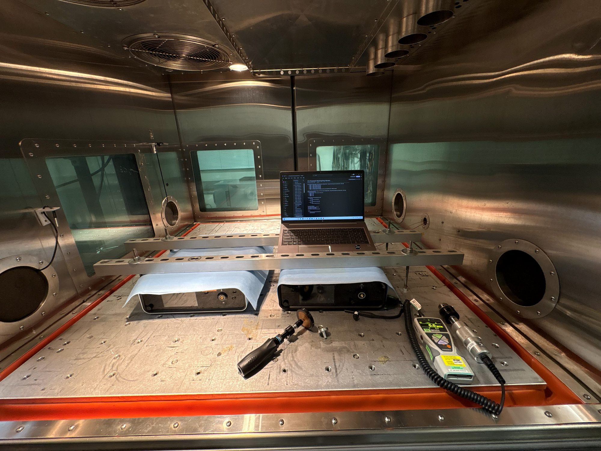
Front cover mounting and cable receptacle changes needed cable receptacle backout resilience verified under vibration.
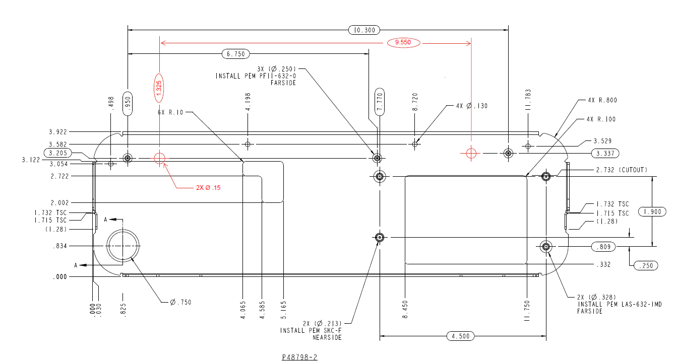
CAD front elevation of a rack-style enclosure cover with connector openings.
02.7 — FRONT COVERRevised front cover mounting and cable receptacle.
An electronics enclosure strapped to a vibration table with instrumentation cables attached.
02.8 — VIBRATION SETUPMounted for vibration testing.
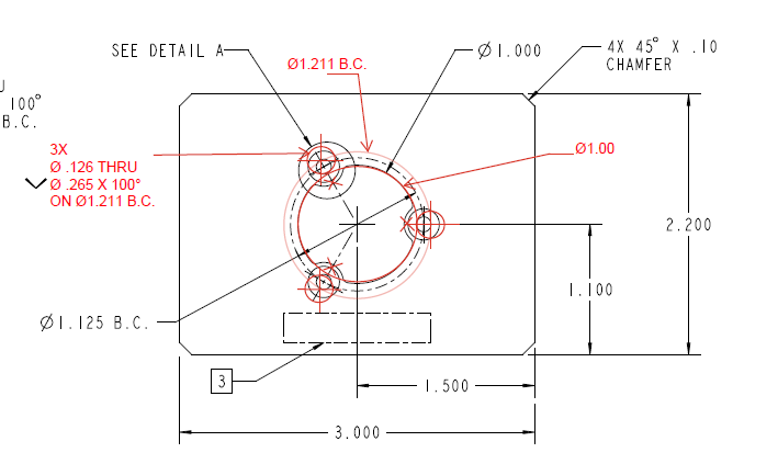
An engineering drawing of a rectangular plate with a bolt circle and chamfer callouts.
02.18 — RECEPTACLE DETAILCable receptacle cutout, dimensioned.
Confidentiality

Proprietary information withheld.

Let’s talk.

Open to co-op, internship and project conversations in mechanical design, product development and R&D.